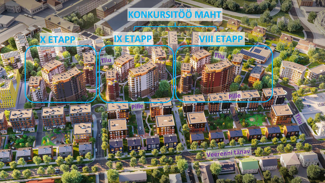
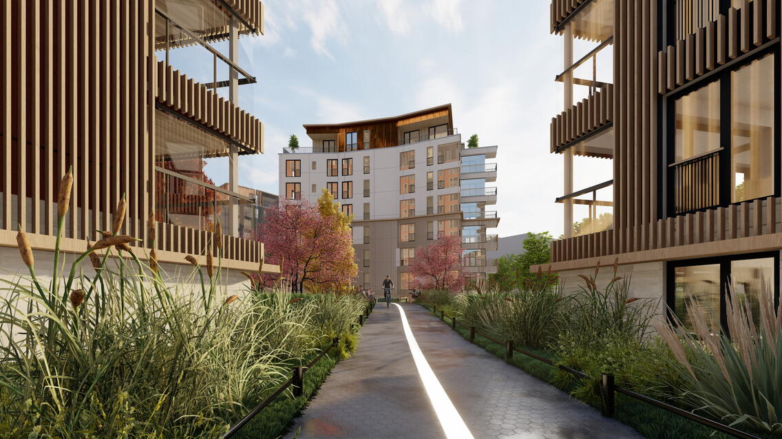
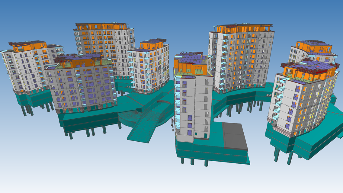
This project concerns the construction of phases VIII and IX of the Uus-Veerenni residential quarter to be developed by Merko Ehitus Eesti AS. The Uus-Veerenni Quarter has been built by Merko since 2018, and phases VIII and IX are a further development, which will place taller buildings in the middle of the residential quarter. In total, there will be 9 houses in the two phases - 5 houses in Phase VIII and 4 houses in Phase IX. In total, there will be 6 different types of houses per phase, the tallest of which will be a 12-storey building of 40.3 meters . The projected buildings and phases will be connected by a common two-storey underground car park.
EstKonsult OÜ is designing the load-bearing structures for both phases. The design of Phase VIII started on 08.2021 and the working design was completed on 01.2023. The design of Phase IX started on 06.2022 and the main design was completed on 05.2023. The product drawings for Phase VIII are still in progress and are largely complete but currently still on the inspectors' desk.
Use of BIM in design
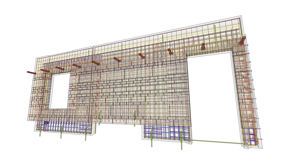
The design of the structures was divided in-house into two parts - the above-ground part and the underground part. The whole above-ground part was modeled with Tekla Structures software and the underground part with Autodesk Revit software. Interaction between the above-ground and the below-ground part was done through IFC models. The IFC models of all the other parties involved in the project were also linked to Tekla and Revit and were used on a daily basis in the design.
For the ground part, one building of each building type (six different building types in total) was modeled in Tekla. In this way, it is possible to ensure that each building type is definitely the same. When generating IFC models, it is possible to output the same building type in different locations.
Trimble Connect, Trimble Connect Sync and BimCollab Zoom software were used to coordinate and control the design work. The models of the different parties were stored in Trimble Connect. In-house, the coordination and control of the design work was mainly done using BimCollab Zoom software. The overall control of the project and the communication with other parties was done in Trimble Connect.
Verification of the IFC models included intersection/conflict checking, visual inspection and also filtered data volume based verification. The latter has also been a great help in double-checking the volumes submitted - to make sure that no systematic errors have been made, which can be difficult to detect within a single piece of software.
The management and coordination of all issues identified and areas to be resolved was handled through the aforementioned IFC dashboards.
Collaboration based on the BIM model
Information was exchanged between the various companies and design teams involved in the project using Trimble Connect and Trimble Connect Sync software. Any issues identified and areas that needed to be resolved generated an 'issue' in the Trimble Connect environment, which was immediately escalated to the right parties. The checking process was multi-stage - models were checked on an ongoing basis by the design project manager. At the end of the various design stages, a thorough check was also carried out by various Merko Ehitus AS employees.
Using different solutions on the construction site
Construction has not yet been completed, but Merko Ehitus Eesti AS teams have been involved in the design from the beginning of the project, and communication, control, etc., has been mainly through Trimble Connect.
Innovation and innovation
The project consists of six main buildings, from which a complete solution has been assembled with nine above-ground buildings. The use of a solution based on typical buildings has its own specificities.
For example:
1) A single model is created for each building type, which is the basis for drawings and IFC models.
2) For each new address, a separate drawing must be issued with correspondingly adjusted bookkeeping.
3) IFC models are issued separately for each building and linked to its real location (both planimetrically and vertically).
4) In addition to the building, the support diagram of the building base section must be representative.
Project management must ensure that the project components are representative.
For example:
1) changing the position of an opening in one building will change the position of the opening in other buildings of the same type.
2) if the architect wants the same type of building to be of a different color, it is sensible to have utilities feed this information into the IFC model and product drawings.
3) In the future Merko Ehitus Eesti AS is planning another phase X of the Uus-Veerenni development, where it will be easy to use the designed standard buildings and drawings.
A number of utilities were written and used to build the Tekla model based on the Tekla Open API.
Some examples:
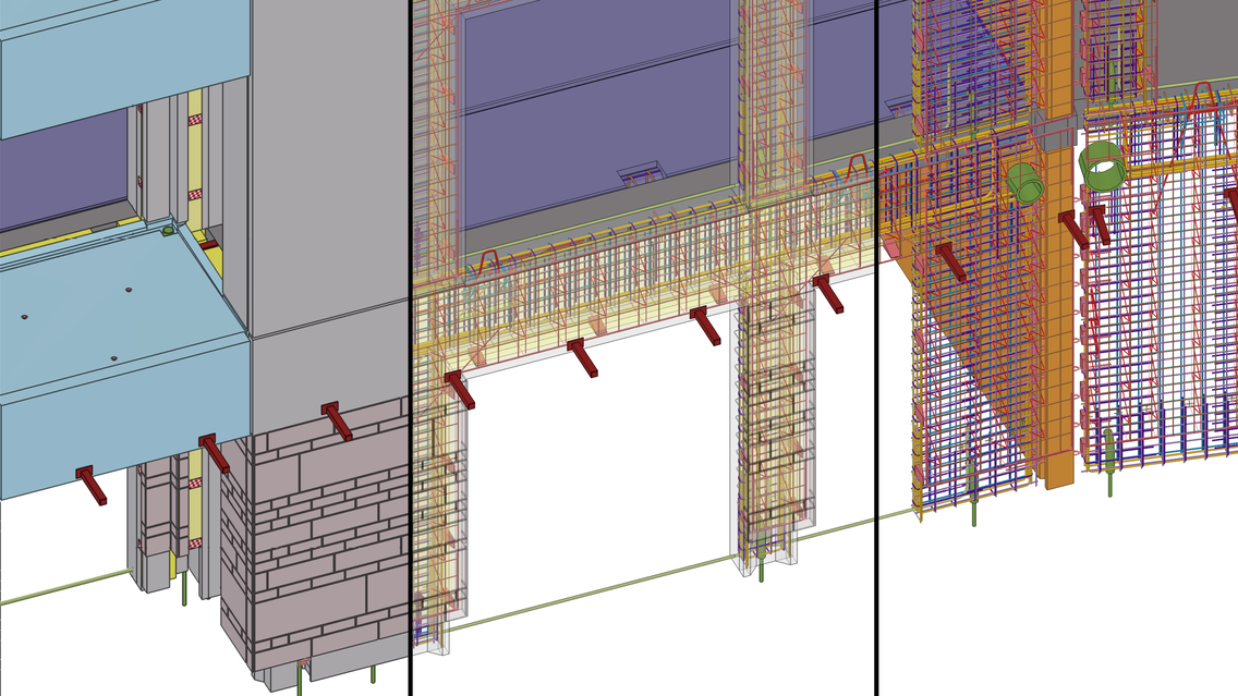
1) A utility for adding electrical boxes and cable conduits to concrete products
The electrical designers provided a baseline specification for electrical conduits and cable trays in the form of an IFC model. EstKonsult provided the electrical designers with instructions on the requirements that the IFC model and the objects should meet in order to be easily made into Tekla elements. The IFC objects obtained from the electric were then converted into Tekla elements using Tekla. A written helper program identified geometrically to which element each electrical object should go, and further inconsistency checks could be performed using the same program. The utility then added each electrical object to the correct product.
2) A utility to cut from the right element
The technical systems designers provided the basic drawings of openings and recesses in the form of an IFC model. There were thousands of openings and items to be cut, and the aim was to avoid unnecessary "cut" elements. To this end, a utility was written to geometrically identify which element each opener should cut, and additional inconsistency checks could be performed using the same program. The helper program then cut the correct elements with the correct opener.
3) Custom property
Determined the position of the center of gravity of each concrete element in a local coordinate system with respect to the starting point of the product. The written 'Custom property' made it possible, for example, to analyze the thickness positioning of the lifting beam of three-layer wall panels and the choice of lifting beam product. As a result of the analysis, four thickness positions of the lifting lugs were selected in such a way that the tilting of the triple-skin panel on the slab during lifting would not be problematic. In addition, it was possible to attach the correct lifting lug to the panels on the basis of the same 'custom property'. The written 'custom property' was also used in the 'custom' component of the lifting lugs.
4) Sustainability
For the design of building structures: Modern software and a professional team were used to optimize the load-bearing structures, with a view to both the cost of materials and the execution of the works. In doing so, cold storage was minimized.
Overall:
According to the client's brief and also the issued design, the building has an energy rating of A class. In order to save electricity costs and to reduce the environmental footprint, solar panels have also been provided on the roofs.
In order to reduce energy consumption and save energy, the buildings will be low-energy and energy-saving by reducing energy consumption. Merko Ehitus Eesti AS is known for its very good construction quality, which, combined with professional designs and proper maintenance of the buildings, will ensure a long lifetime of the buildings.
Project parties:
Engineering office.
Developer and constructor: Developer and developer.
Architectural design and main design: Arhitektuuribüroo Pluss OÜ.
Interior architecture: Lävi OÜ
EstKonsult Keskkonnatehnika OÜ: Lävi OÜ Lävi Design and Construction
Sprinkler: Firetek OÜ
Electricity and automation: Meliorprojekt OÜ
Fire safety: Rovalis OÜ

