BIM is important for safe construction in a trafficked area
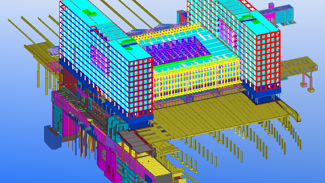
YIT utilizes some of the frame of an existing station building to expand and renovate the busy railway junction in Pasila, Helsinki, as part of a major building project called Tripla. The railway tracks remain in use during construction while one new track is added to the west side of the complex. The project includes demolition of the old station building up to current customer service level. The structures to be kept are to be reinforced and renovated so that they will last the required 100 years. Upper part of the station is built as a new construction.
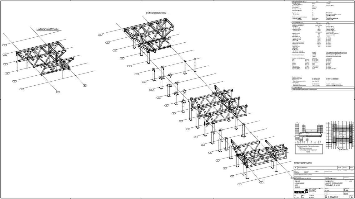
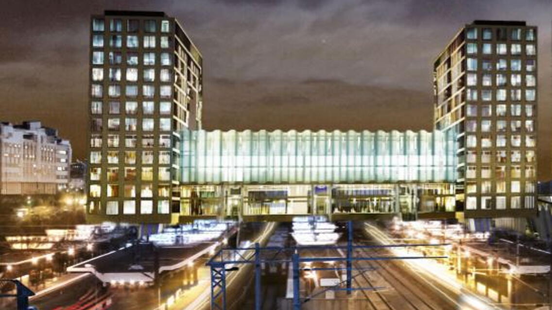
Current building to be renovated has three floors above-ground, a platform level and two basement levels. Eventually, approx. 100,000 people are expected to pass through the station daily, and 3,500 people will work in the building. The new building is divided into three sections, two office towers on the sides and one lower building in the middle housing premises for commercial services such as restaurants, gyms and offices, and an engine room for the ventilation systems. The project covers a gross area of 62,000 m2. The new complex will include 12 above-ground floors, a platform level, and six basement floors. Rock surface in the area varies greatly in steepness, and the lowest point of the foundations is approx. 22 m under ground level. The old building frame will be reinforced with piles and by extending its cross section to function as a base for the office towers. The offices will be carried by a bridge structure on level +40 that will also function as a load
division structure in case of an accident.
A new railway track, passenger terminal and reservation for a metro station will be built on the west side of the station. In order to enable the transformation, a temporary station with pedestrian bridge has been built and is in use on the north side of the station. All passenger traffic is directed to this temporary station during the construction work.
A demanding project in many ways
The whole construction project is carried out in a fully functional railway area. Keeping the traffic going without breaks places great demands on the schedules and safety on-site. Accidents during construction or while the building is being used, and the consequences thereof may be severe, and a fault or damage in the structures may cause vast human loss or social impact. Structurally, the project has been classified in the most demanding category CC3b, and its structural design also ranks in the most demanding design categories for various reasons.
Constant railway traffic through the site makes construction more difficult, and a train going off course or setting on fire may damage the uncompleted structures. The buildings are founded on the reinforced old frame that will be transformed essentially by demolishing eight columns to make room for the western track. The design includes the railway bridges as well as street and metro station structures.
Foundation conditions are extremely demanding due to highly aggressive sulfite clay and polluted soil. Consequence category CC3b requires that any load-bearing vertical structure can take possible damage and that all loads must have alternative bearings. The bridge structure located in the intermediate floor on level +40 is highly demanding and massive, and the use of these kinds of structures causes many building-physical challenges. Coordinating vertically diverse spaces, caves and railway structures requires highly advanced methods.
All project participants committed to using BIM
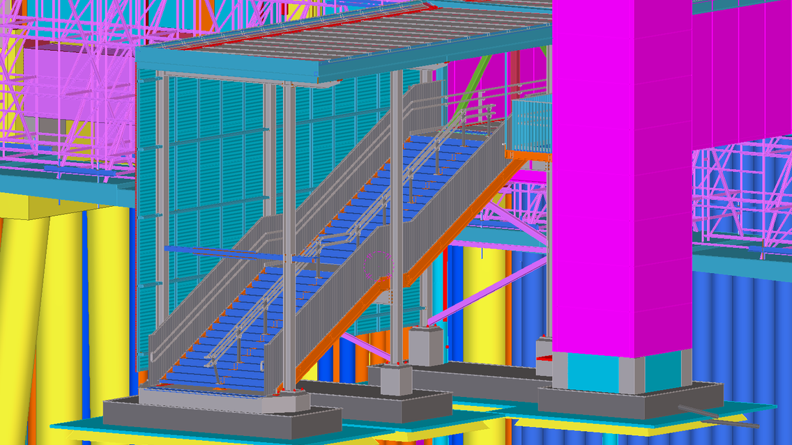
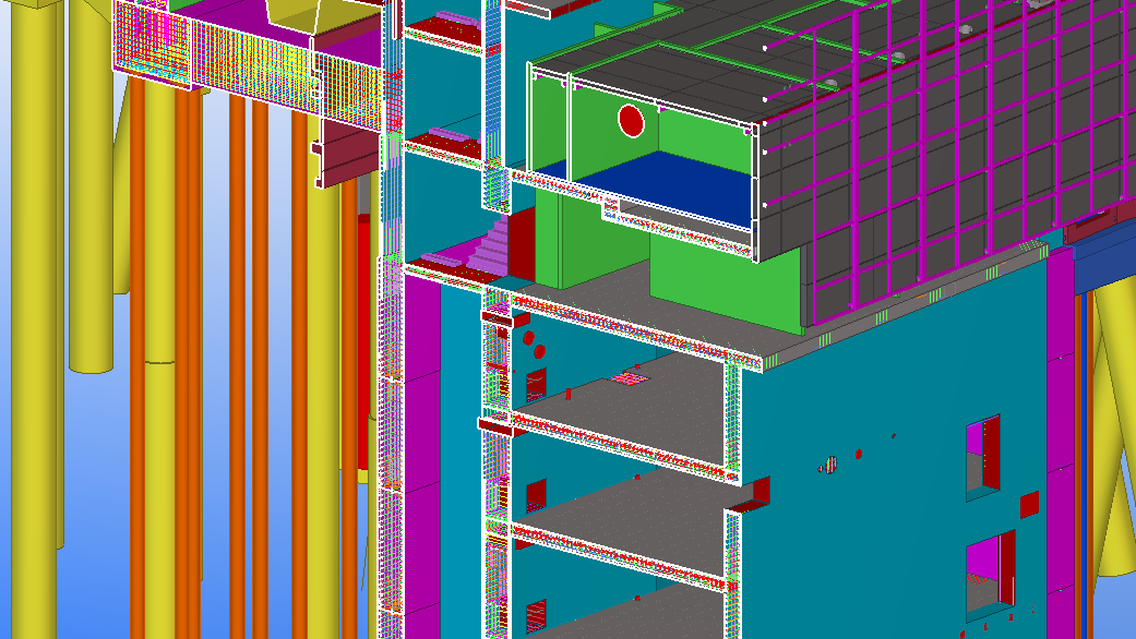
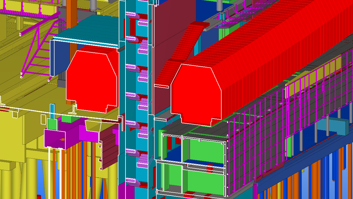
All the design disciplines have delivered their reference models to the project, and all project participants are committed to the use and further utilization of the building information models. A dedicated local coordinate system was defined for all participants to share. The combination models created by the BIM coordinator, the clash check meetings and the Big Room method have been of help in the project. Design work started by laser scanning the old structures and using the data to make a comprehensive inventory model. Tekla Structures was used to make a reconstruction of existing load-bearing structures based on the inventory model and old plans. All cast-in-place structures have been modeled and steel parts have been detailed. Also, temporary steel structures have been modeled regarding demolition. The structures of non-bearing walls are exported from model to ELiPLAN for element fabrication.
Structural clash checking was felt to be much easier and the design of higher quality in 3D compared to 2D. Tekla Structures can fit in more input data needed by each designer, and the program was also used in scheduling by copying the desired tasks from PlaNet to Tekla Task Manager and attaching them to respective objects in the structural model. After assigning the tasks, their planned start and end dates and color codes, the software was able to find tasks according to date and visualize what should have been completed so far. The upper part of Tekla model is shared to the site using Tekla Model Sharing and erection status is marked on the model. Mobile use of Tekla Field3D on-site was more effective in the frame and interior phase when mechanical equipment was added. Site foremen have tablets and plans are checked and compared on-site. Tekla BIMsight was used in meetings and combining the models of all the project parties. In addition, modeling was used to create hole reservations.
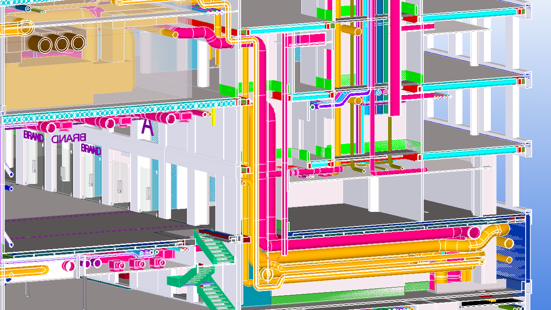
Revit Live is used for visualizing IFC files of structural engineering in VR using HTC Vive glasses. Construction site planning is BIM based (using link with Revit and Autodesk A360) and structural designer’s models are used in the planning. The site model is used in planning the logistics of the site and in site personnel orientation to the site. Solibri Model Checker is used to share model information between designers and to integrate the plans. The differences in dimensions of the load-bearing and stiffening structures between structural model and architectural model are dealt in the models before moving to production.
Project parties
General contractor: YIT Rakennus Oy
BIM coordinator: Gravicon Oy
Structural design: Sweco Rakennetekniikka Oy, Sito Oy
Architects: Sweco Architects Oy, Arkkitehdit Soini & Horto Oy
HVAC and sprinkler design: Ramboll Finland Oy
Electrical design: Granlund Oy
Waste collection system design: Marimatic Oy
Geotechnical design: Ramboll Finland Oy
Rock engineering: Sito Oy
Laser scanning and inventor data: Tietoa Finland Oy, Surgeon Oy, YIT Rakennus Oy
Rail and infrastructural design: Sito Oy, WSP Finland Oy, Ramboll Finland Oy
Electrical railway design: Proxion Oy
