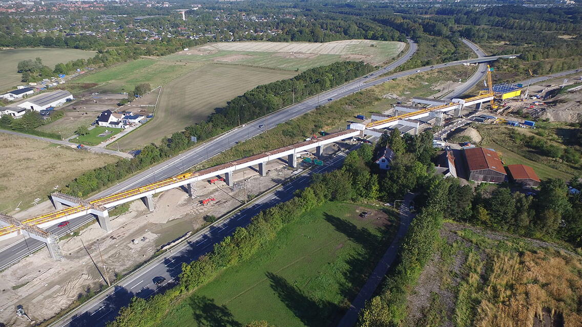
Banedanmark is in the process of building a new double tracked railway between Copenhagen and Ringsted in Denmark. Part of this process is the TP30 contract, a difficult railway overpass across two highways. A composite superstructure with large abutments and portals represents the structural concept of the bridge. This type of structure ensures that the motorway traffic is not disturbed during the construction, which it has been of great importance.
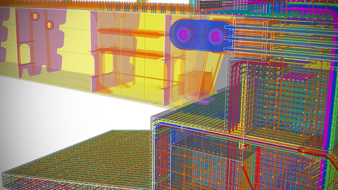
3DSD and CN3 have carried out a number of consulting assignments for the contractor of the TP30 site, CG Jensen A/S. The existing design of all steel and concrete structures in 2D has been assessed and optimized by modelling a detailed BIM model (LOD 500) containing steel and concrete geometry, reinforcement, cast in embeds and temporary structures. The work has led to an iterative optimizations process where the central focus has been to industrialize essential elements in the construction phase.
1.1Industrialization of steel and concrete structures
A tight schedule and challenging logistical conditions on the construction site made it necessary for 3DSD and CN3, in close cooperation with CG Jensen, to reconsider production and execution principles. On this basis, it was possible to optimize structures in regards to production by prefabricating large reinforcement sections off site. This allowed production on site to continue with preparation, establishment of sandbags, dewatering and more, while reinforcement modules were welded under controlled conditions. By using own developed tools with the Tekla API, the reinforcement was divided according to specific characteristics, which made the optimization easy to implement.
Analysis of assembly methods, material weight and relevant dimensions for welded reinforcement cages were continuously evaluated in a 5D interface to directly be able to follow the economic impact of specific design choices. Again, in-house API tools were used to facilitate the 5D integration. Furthermore, the many welded reinforcement cages were manufactured directly using the BIM model for production at the factory, eliminating the need to produce traditional workshop drawings. For several constructions, it was possible to industrialize up to 75% of the reinforcement as prefabricated solutions resulting in increased productivity in the construction phase.
At the construction site, production meetings were held continuously; here, the various solutions for the respective structures were reviewed prior to the start of production. In addition, assembly instructions were provided for the sections that were delivered welded at the construction site and which constantly needed to be integrated with traditional cut and bent reinforcement.
1.2Additional usage for coordination on site
The working environment was regularly assessed so that delivered cut ant bent reinforcement could be built in, while larger reinforcement groups with high density were placed in the welded elements. In the large abutments, prefabricated reinforcement elements exceeding a weight of 5 tons, were designed. Some reinforcement groups were highly complex and had to be supported by temporary structures during the execution phase. In this context, CN3 contributed with a design solution, in which welded steel frames were produced and installed as framework before the assembly of prefabricated reinforcement towers. Hereby the critical tolerances, in relation to other structures and more, could be met. CN3 transferred the reinforcement towers and additional steel frames into a FEM analysis software and supplied static documentation concerning behaviour of the framework.
1.3Shop drawings and workshop 3D models
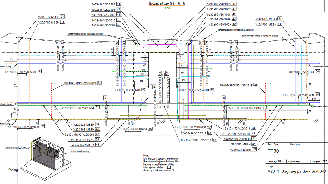
A design coordination has been conducted in close collaboration between 3DSD (Steel) and CN3 (Concrete). The reinforcement has been assembled on a production facility (welded cages) and on site through extensive use of Tekla BIM Sight. Due to a very tight time schedule, it was only possible to carry out some main drawings of concrete and reinforcement, while most of the reinforcement was produced direct through use of tablets. The reinforcement was handed over to the manufacturing process by the bvbs format for digital production.
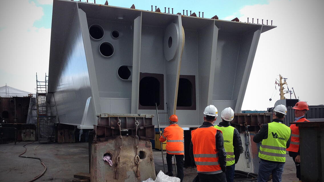
3DSD has prepared the complete set of shop drawings for the steel structures in the portals and the deck sections for the bridge. These drawings are based and generated from a complex Tekla model where all steel detailing has weld preparations included.
In relation to this, the bridge deck geometry has been unequivocally defined so that concrete and not least the reinforcement work can be executed after the mounting of the large steel construction.
The detailing In Tekla Structures by 3DSD and CN3 has been based upon the 2D drawings and descriptions prepared by the engineering company ISC Consulting Engineers A/S.


