not-allowed-link

The new Rappenloch bridge

Using a 3D model for coordination helped prevent possible collisions and problems on the construction site.

About the project

Project category

Infrastructure

Company

LGB Operations GmbH

Location

Austria

Images

Project in numbers

Longitudinal inclination

10.5%

Total length

66 m

Trimble products used

Tekla Structures

The new Rappenloch bridge

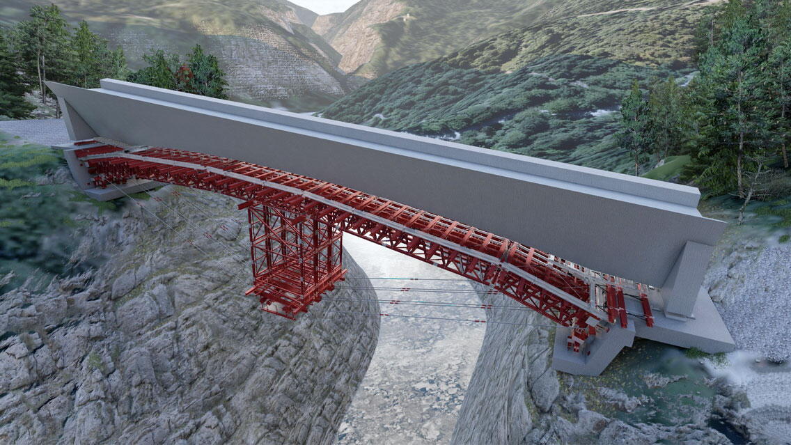
The new Rappenloch bridge is a single-track prestressed concrete bridge. The total length of the superstructure is about 66m. The cross-section of the box girder bridge is designed as a triangular cross-section in the abutment area and warps towards the middle to a trapezoidal box girder cross-section.

The cross-section height changes from 5.7m to 3.3m. The structure has a longitudinal inclination of 10.5%. The lower edge of the bridge shows a slight arch with a rise of 2.4m.

Due to the Dornbirner Ach running below, a free-span shoring had to be used to build the bridge. Appropriate bearing surfaces were provided below the abutments for this purpose. Due to the limited accessibility caused by the very narrow access road, a shoring system that was as light as possible had to be developed. 

The maximum weight of the individual parts in the crown area is limited to approx. four tons, and the full length of the components that can be delivered via the existing road is 12 m. 

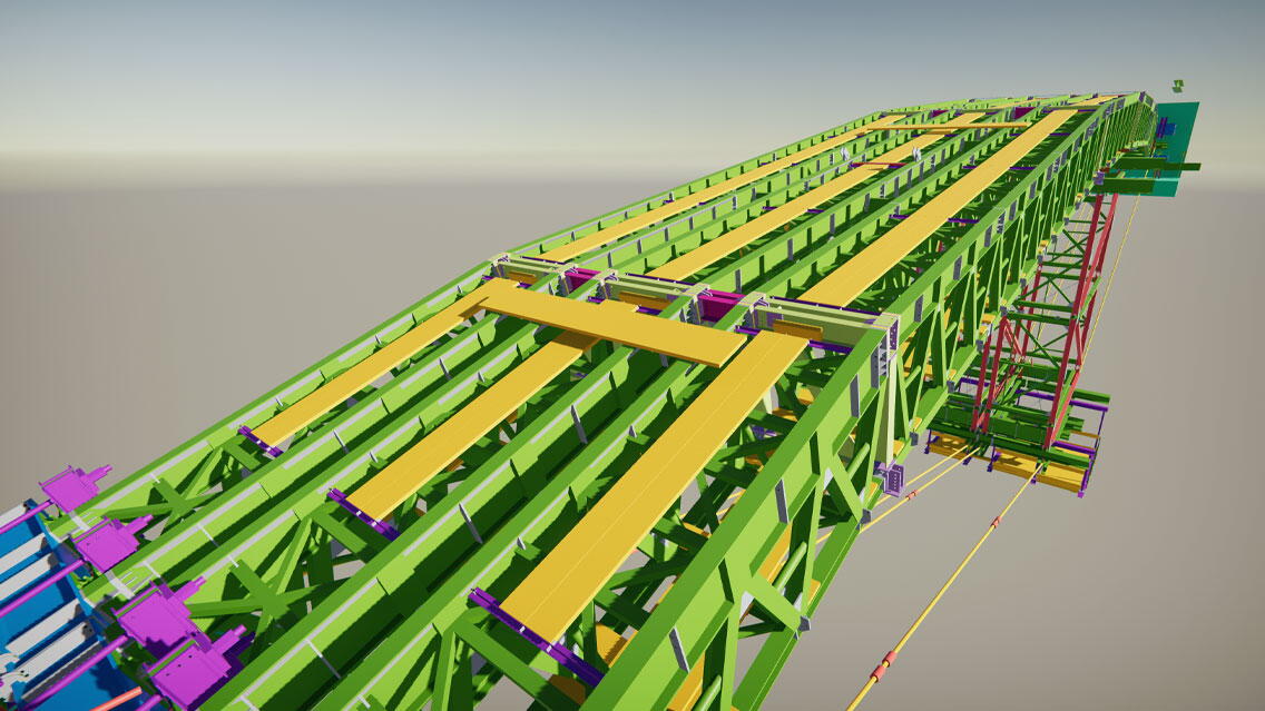
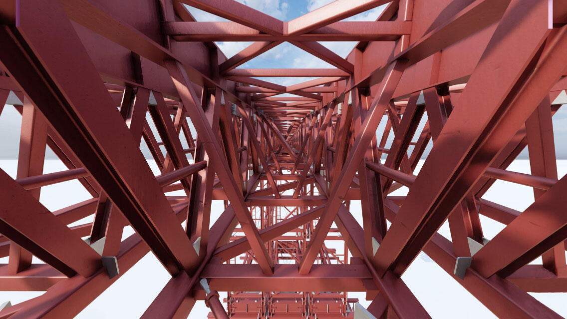
Due to these boundary conditions, a technically complex shoring had to be developed. We then developed a gently sloping arch support structure consisting of 3 truss tubes. The lattice trusses are restrained to the transoms for assembly and to increase the load-bearing capacity. To ensure the static load-bearing capacity in the concreting state, the shoring had to be braced with tie rods.
 

Assembly of the falsework

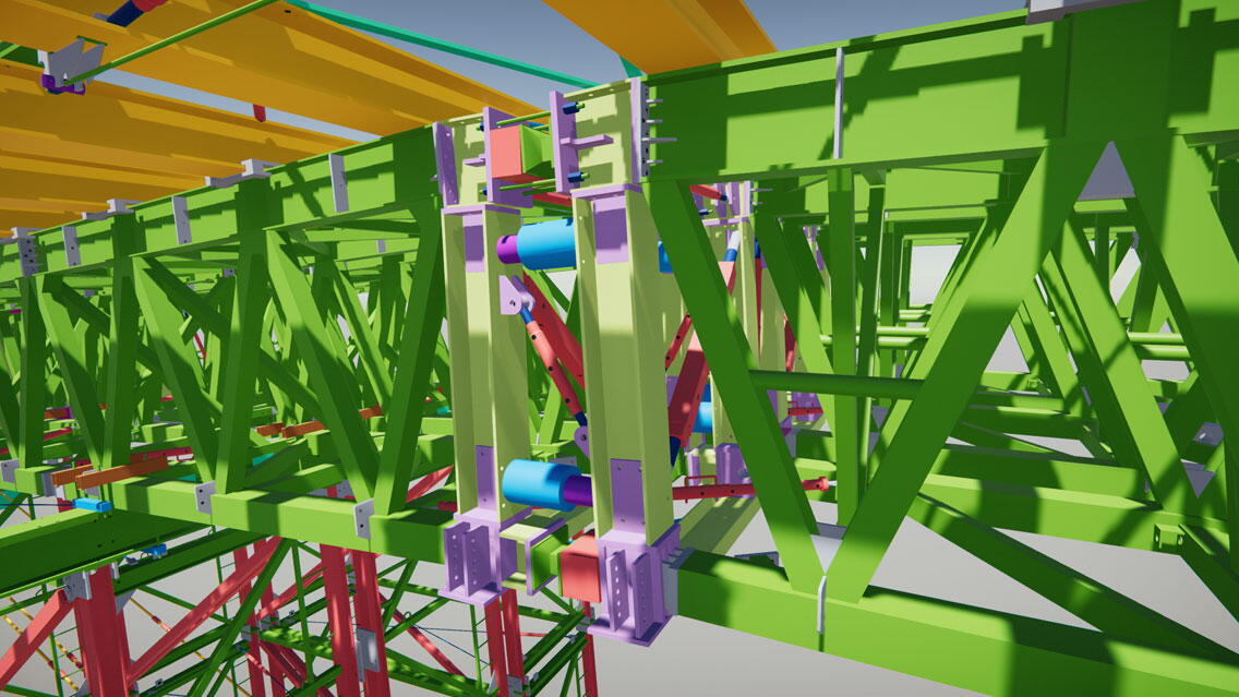
Due to the limited accessibility, the trusses are assembled in small units. We, therefore, decided to mount the lattice trusses so that they cantilevered from both sides. On the Dornbirn abutment side, the inner truss is hung back to an assembly yoke using anchor rods.


Concreting state

The superstructure is made in several concreting steps. We included these construction phases in the static calculation accordingly.
 

Disassembly

For dismantling, the trusses are hung on the completed superstructure and moved laterally. The components are then dismantled piece by piece.
 

Conclusion

All planning processes were done in Tekla Structures, including all intermediate states during assembly and disassembly.
 

Tekla BIM Awards

The Tekla BIM Awards honor projects that transform the way the world builds.

See all projects

The Content on this page is provided to Trimble Solutions Corporation ("Trimble") under the Tekla Global BIM Awards Terms and Conditions.

Trimble Logo

INTERNATIONAL (ENGLISH)

globe wireframe
magnifying glass
Tekla logo

Productscaret icon

Tekla Structures skip iconTekla Model Sharing skip iconTekla Structural Designer skip iconTekla Tedds skip iconTekla PowerFab skip iconTrimble Connect skip iconAll products skip icon

Solutions downward-facing caret

Designright caret

Constructible modeling skip iconConceptual design skip iconStructural analysis & design skip iconDesign communication skip iconConnected design skip icon

Detailright caret

Constructible detailing skip iconConstruction documentation skip icon

Fabricateright caret

Production planning & management skip iconAutomated production skip iconConnected project delivery skip icon

Constructright caret

Bid & win skip iconSite planning & coordination skip iconConnected worksite skip icon

Educateright caret

Tekla Campus skip iconTekla for students skip iconTekla for educators skip iconTekla for academic institutions skip iconTrimble student ambassador program skip icon

All solutions

Resourcescaret icon

Articles & blog posts skip iconReferences skip iconWebinars skip iconNews skip iconEvents skip iconeBooks skip iconTekla BIM Awards skip iconAll resources skip icon

Supportcaret icon

Tekla User Assistance skip iconTrimble Downloads skip iconTekla Discussion Forum skip iconTekla Warehouse skip iconTekla Developer Center skip iconTraining skip iconAll support skip icon

Aboutcaret icon

Why Tekla & Trimble skip iconContact us skip iconCareers skip iconTekla Trust Center skip iconLicense compliance skip iconAll about skip icon

| INTERNATIONAL (ENGLISH)

globe wireframe icon

Productscaret icon

  • Tekla Structures
  • Tekla Model Sharing
  • Tekla Structural Designer
  • Tekla Tedds
  • Tekla PowerFab
  • Trimble Connect
  • All products

Solutionscaret icon

Designcaret icon

  • Constructible modeling
  • Conceptual design
  • Structural analysis & design
  • Design communication
  • Connected design

Detailcaret icon

  • Constructible detailing
  • Construction documentation

Fabricatecaret icon

  • Production planning & management
  • Automated production
  • Connected project delivery

Constructcaret icon

  • Bid & win
  • Site planning & coordination
  • Connected worksite

Educatecaret icon

  • Tekla Campus
  • Tekla for students
  • Tekla for educators
  • Tekla for academic institutions
  • Trimble student ambassador program
All solutions

Resourcescaret icon

  • Articles & blog posts
  • References
  • Webinars
  • News
  • Events
  • eBooks
  • Tekla BIM Awards
  • All resources

Supportcaret icon

  • Tekla User Assistance
  • Trimble Downloads
  • Tekla Discussion Forum
  • Tekla Warehouse
  • Tekla Developer Center
  • Training
  • All support

Aboutcaret icon

  • Why Tekla & Trimble
  • Contact us
  • Careers
  • Tekla Trust Center
  • License compliance
  • All about
  1. Home
  2. Tekla BIM Awards
  3. The new Rappenloch bridge
CONTACT US