not-allowed-link

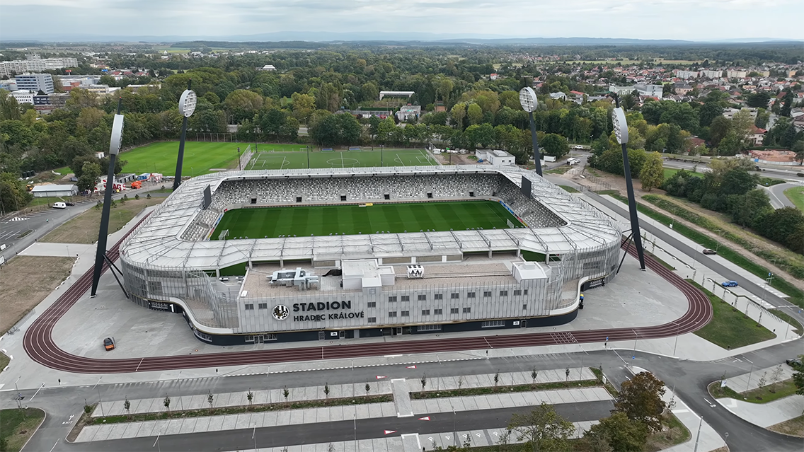
Multifunctional football stadium Hradec Králové

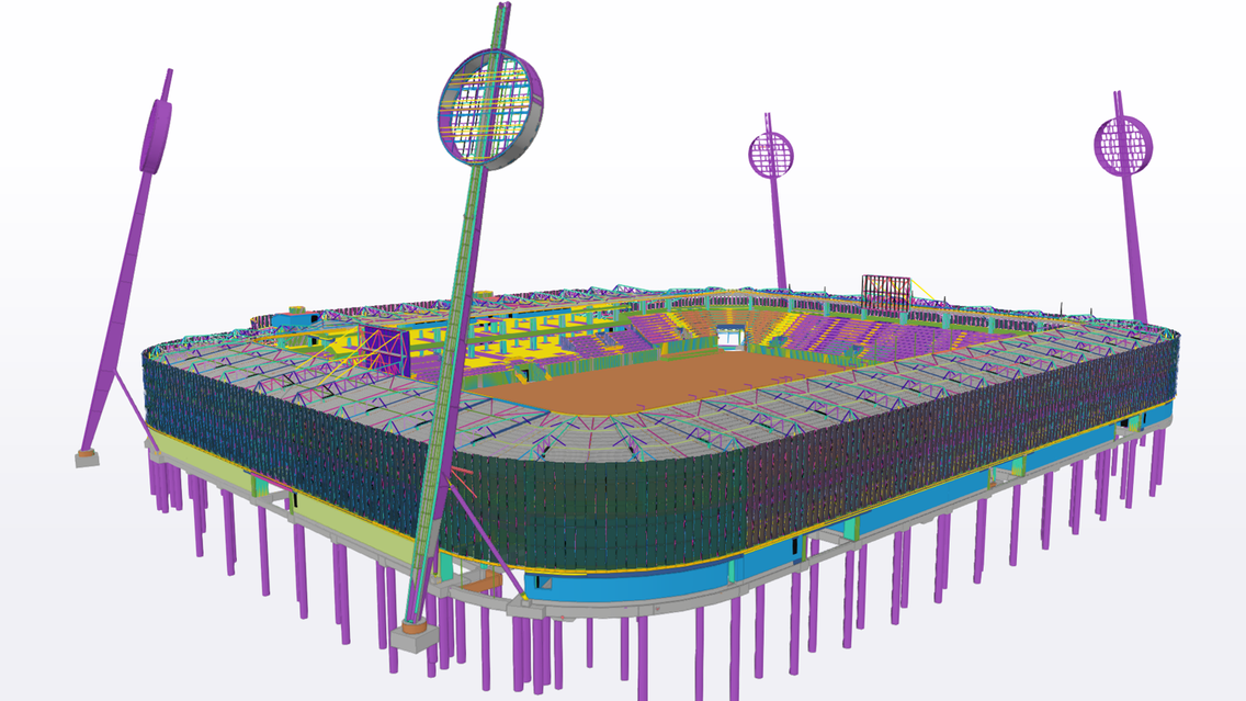
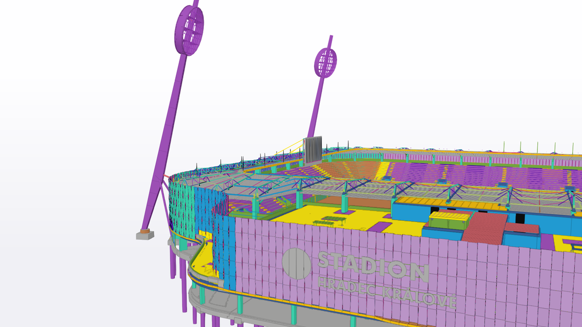
Steel and reinforced concrete structures were modeled using one common model in the Tekla Structures program.

About the project

Project category

Sports & Recreation

Company

Skála & Vít s.r.o.

Location

Czech Republic

Images

placeholder imageplay button

Project in numbers

Capacity

9,300 seats

Cost

763 million CZK

Trimble products used

Tekla Structures, Trimble Connect

Multifunctional football stadium Hradec Králové

  • Investor: Statutory City of Hradec Králové
  • Construction method: Design & Build
  • Architect: Tomáš Vymetálek Architects
  • Chief designer: ARCHaPLAN
  • Construction: SKÁLA & VÍT
  • Construction contractor: association of the Strabag, Geosan Grup, D&D Elektromont
  • Capacity: 9300 spectators, all places covered, intended for sitting
  • VIP space capacity: 500 seats
  • Skybox capacity: 210 seats
  • Start of construction work: August 2, 2021
  • Approval: August 2, 2023
  • First match: 5 August 2023
  • Grand opening: September 3, 2023

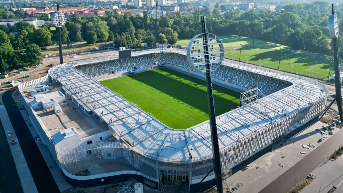
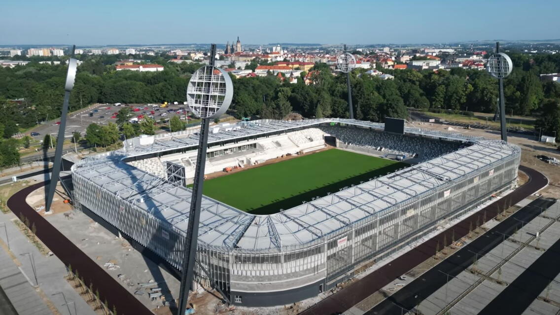
The Malšovická Arena was built in 2022 and 2023 on the site of the former All-Sports Stadium in Hradec Králové. It was built in 1970, and fifteen years later the famous lollipops were added to it, which were preserved even for the new arena.
For several years, the historic stadium did not meet the standards of the first league, so it had to be replaced with a modern sanctuary. After Hradec Králové returned to the top competition, the Votroci had to move to the Lokotrans arena in Mladá Boleslav for the 2021/22 and 2022/23 seasons. Here, they had to wait until the construction of the new multifunctional arena was completed.
The construction of a modern multifunctional stadium in Malšovice was approved in March 2021, and the construction was undertaken by an association of companies Strabag, Geosan Group and D&D Elektromont.
The arena, which will be inaugurated on September 3, 2023, cost 763 million CZK, including VAT. Its capacity will be 9,300 seats, making it one of the largest football stadiums in the Czech Republic.

PROJECT:

The stadium was already divided into two parts in the study.
The first part (north, east and south), connected at the corners by transitional arch stands, consists of monolithic reinforced concrete structures and a galvanized steel roofing structure.
The second (western) part consists of a monolithic reinforced concrete three-story skeleton with a roof structure, a monolithic part of the stands and a galvanized steel roofing structure.
The facade around the stadium's perimeter was designed using a system of galvanized posts and horizontal elements. The filling consists of expanded metal.

WORKING USING TRIMBLE SYSTEMS:

A) The company Geodézie Východní Čechy spol. s r. o. used leveling devices for precise leveling Trimble DiNi03
B) Trimble Bussines Center software was provided by Geodézie Východní Čechy spol. s.r.o. used to :
1) Calculate all the cubic volumes of earthworks on the construction site. Due to the great fragmentation at the construction site, the data was usually obtained using aerial photogrammetry (from a UAV) and evaluated from point clouds.
2) Calculate leveling programs, focused using the above-mentioned Trimble DiNi03 device
3) Compare targeted heights on the construction site and digital models of the terrain that were part of the construction project (e.g. to check the plan of the surrounding roads and the playing area)
4) Edit, display, evaluate and prepare digital models of the plains' terrain so that the project data can be transferred to the terrain as efficiently as possible. Subsequently, these models are uploaded to the total station, and the values from the DMT are plotted directly in the terrain.
C) Steel and reinforced concrete structures were modeled in the TEKLA Structures program by SKÁLA & VÍT, s.r.o. in one common model. This ensured the coordination of steel and reinforced concrete structures at the point of connection.
 

Processed levels of documentation:
1) Change of construction before completion
2) Implementation project
3) Production and assembly documentation of steel structures
4) Supplier documentation of reinforced concrete structures
5) Documentation of the actual execution
D) The Trimble Connect program was used to coordinate professions using 3D models.

REINFORCED CONCRETE STRUCTURES

The Foundation
Deep-drilled piles were chosen as a foundation on the basis of an engineering-geological survey. The placement of the piles is based on the arrangement of the upper load-bearing structure. The piles are equipped with monolithic reinforced concrete pad footing, which is connected by monolithic reinforced concrete strip footing for the transmission of horizontal forces and in the places where the brick load-bearing perimeter walls are established.
West Stand
The monolithic reinforced concrete three-story skeleton is made up of vertical columns, stiffening wall stair cores and a ceiling reinforced by headers and flat beams. A separate part is the outdoor VIP monolithic inclined tribunes supported by vertical columns and inclined beams. The basic module system of columns is 8.0m in the longitudinal direction, 5.8m + 7.5m + 5.7m + 5.1m in the transverse direction.
North, East and South stands.
In the transverse direction, the structure of the stands is made up of a monolithic reinforced concrete frame made of three columns and an inclined beam. A monolithic reinforced concrete construction of sloping stands in the shape of steps is placed longitudinally on the frames, which are divided into expansion units. In every other field, there are "moon gates" - monolithic reinforced concrete walls with a staircase. The module axes of the transverse frames are 9.6 m apart on the east stand and 10.1 m on the north and south stand.
Around the entire perimeter, there are built-ins under the stands, with a background of brick load-bearing walls and a monolithic reinforced concrete ceiling.

STEEL CONSTRUCTIONS

Roof construction
The main supporting element of the steel roof above the stands is galvanized truss beams with a cantilevered length of approximately 14 m, going from the head of reinforced concrete columns. Trusses are welded from rolled H-shaped cross-sections and diagonals, with verticals from rectangular and square hollow cross-sections. The galvanized truss beam has the shape of a quadrilateral.
The height of the truss is the highest above the head of the reinforced concrete, and the height is the smallest at the extremity of the cantilever. The height above the column is approximately 1,700 mm. The lower belt of the truss is inclined into a slope towards the outer contour of the stands.
The galvanized trusses of the northern, eastern and southern stands are supported from the bottom by galvanized struts of square hollow sections. These struts are located approximately one-fifth of the cantilevered length of the lower belt of the truss and approximately 2 m below the head of the concrete columns.
The galvanized trusses of the western stand are designed in the same sense. The only difference is the roof slope and the absence of struts. The height above the ground at the extremity of the cantilevered part is preserved, and thanks to the lower roof slope a higher level of support on concrete columns is achieved.
At the level of the lower belt of the truss, there are connected galvanized purlins of square hollow cross-sections. At a distance of 2 m from the truss, the purlins are suspended by tie rods of circular hollow cross-sections suspended from the upper belt of the truss. The outer purlin at the extremity of the truss cantilevered part is not suspended but forms a continuous beam.
The transition fields of the roof at the west stand where the roof slope changes are created using bent galvanized purlins and a skew galvanized beam to support galvanized trapezoidal sheets.
Under the lower belts of the truss and in the middle span of the purlins, brackets made of circular hollow cross-sections are attached, which carry the beams made of pairs of U-sections oriented along the slope of the roof. The roof galvanized trapezoidal sheets of height 135 mm are inserted into the beams of pairs of U-sections and serve as a bearing part of the roof. Wooden boards and PVC waterproofing films are attached to the galvanized trapezoidal sheets.
Behind the football targets on the north and south stands, there are structures for fixing the flat screens, which measure approximately 6.9 x 10.6 m and are attached to two atypical trusses with additional struts and bracings.
Construction of facades
The facade around the perimeter of the stadium is made up of T-section posts with a variable web height welded from a metal sheet. The posts are connected at the base to the reinforced concrete wall around the stadium. The next supports of posts are in two levels by thin-walled C-shaped wall rails. The last part of the post forms a cantilever.
Between the posts, metal angles of bent sheets are attached, which carry expanded metal sheets with a maximum filling ratio of 50%.
Other constructions
Stairs, railings, platforms, cooling/air conditioning units etc., are made of galvanized steel structures.
 

Tekla BIM Awards

The Tekla BIM Awards honor projects that transform the way the world builds.

See all projects

The Content on this page is provided to Trimble Solutions Corporation ("Trimble") under the Tekla Global BIM Awards Terms and Conditions.

Trimble Logo

INTERNATIONAL (ENGLISH)

globe wireframe
magnifying glass
Tekla logo

Productscaret icon

Tekla Structures skip iconTekla Model Sharing skip iconTekla Structural Designer skip iconTekla Tedds skip iconTekla PowerFab skip iconTrimble Connect skip iconAll products skip icon

Solutions downward-facing caret

Designright caret

Constructible modeling skip iconConceptual design skip iconStructural analysis & design skip iconDesign communication skip iconConnected design skip icon

Detailright caret

Constructible detailing skip iconConstruction documentation skip icon

Fabricateright caret

Production planning & management skip iconAutomated production skip iconConnected project delivery skip icon

Constructright caret

Bid & win skip iconSite planning & coordination skip iconConnected worksite skip icon

Educateright caret

Tekla Campus skip iconTekla for students skip iconTekla for educators skip iconTekla for academic institutions skip iconTrimble student ambassador program skip icon

All solutions

Resourcescaret icon

Articles & blog posts skip iconReferences skip iconWebinars skip iconNews skip iconEvents skip iconeBooks skip iconTekla BIM Awards skip iconAll resources skip icon

Supportcaret icon

Tekla User Assistance skip iconTrimble Downloads skip iconTekla Discussion Forum skip iconTekla Warehouse skip iconTekla Developer Center skip iconTraining skip iconAll support skip icon

Aboutcaret icon

Why Tekla & Trimble skip iconContact us skip iconCareers skip iconTekla Trust Center skip iconLicense compliance skip iconAll about skip icon

| INTERNATIONAL (ENGLISH)

globe wireframe icon

Productscaret icon

  • Tekla Structures
  • Tekla Model Sharing
  • Tekla Structural Designer
  • Tekla Tedds
  • Tekla PowerFab
  • Trimble Connect
  • All products

Solutionscaret icon

Designcaret icon

  • Constructible modeling
  • Conceptual design
  • Structural analysis & design
  • Design communication
  • Connected design

Detailcaret icon

  • Constructible detailing
  • Construction documentation

Fabricatecaret icon

  • Production planning & management
  • Automated production
  • Connected project delivery

Constructcaret icon

  • Bid & win
  • Site planning & coordination
  • Connected worksite

Educatecaret icon

  • Tekla Campus
  • Tekla for students
  • Tekla for educators
  • Tekla for academic institutions
  • Trimble student ambassador program
All solutions

Resourcescaret icon

  • Articles & blog posts
  • References
  • Webinars
  • News
  • Events
  • eBooks
  • Tekla BIM Awards
  • All resources

Supportcaret icon

  • Tekla User Assistance
  • Trimble Downloads
  • Tekla Discussion Forum
  • Tekla Warehouse
  • Tekla Developer Center
  • Training
  • All support

Aboutcaret icon

  • Why Tekla & Trimble
  • Contact us
  • Careers
  • Tekla Trust Center
  • License compliance
  • All about
  1. Home
  2. Tekla BIM Awards
  3. Multifunctional football stadium Hradec Králové
CONTACT US