Load-bearing structures for luggage sorting technology
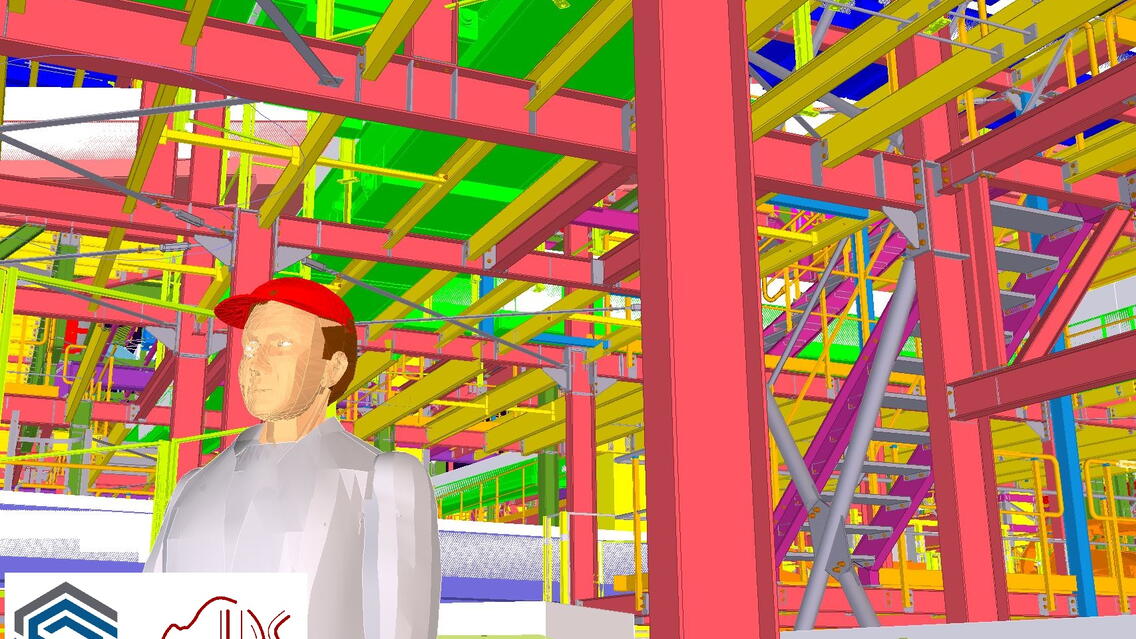
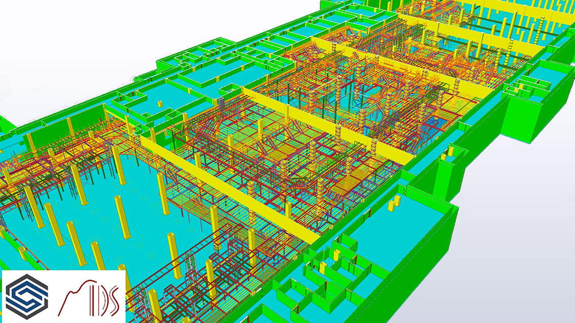
It is an indisputable fact that without the modern tools Tekla Structures Steel Detailing, Tekla Model Sharing, and Trimble Connect, the whole process could not run at such a pace and with such quality. All resource documents and assignments were handed over in the form of 3D models and data.
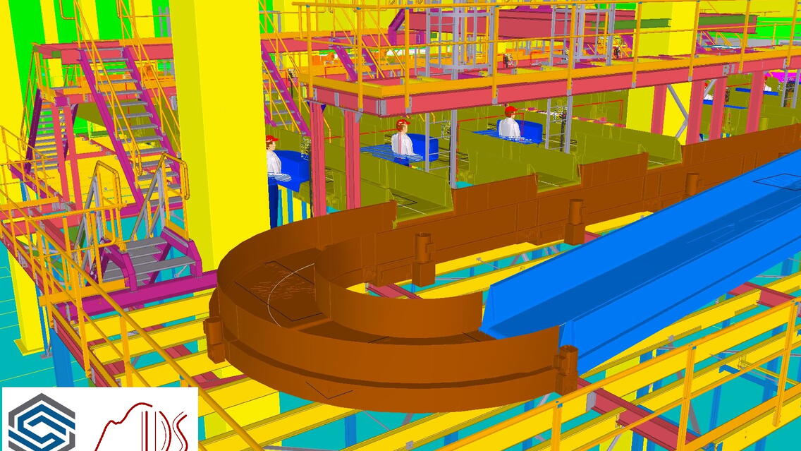
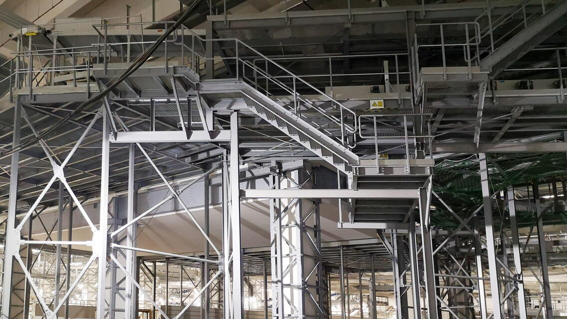
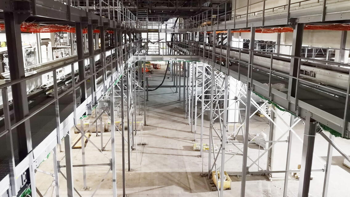
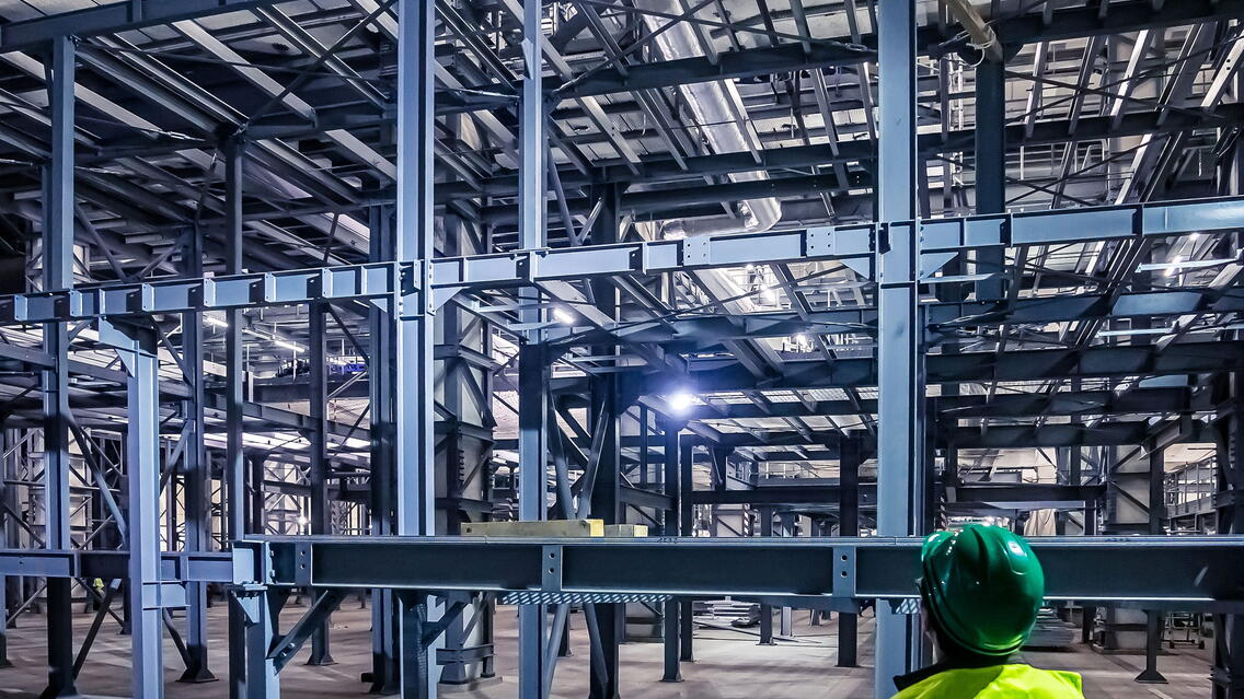
These are load-bearing structures for luggage sorting technology. The reason for the construction was to expand the capacity of the international airport terminal. All structures are located indoors and below ground level. The whole project is divided into three parts – ’A’, ’Gallery’ and ’B’. Part ’A’ has rough floor plan dimensions of 60 x 208 meters and a maximum height of 12 meters. It is a multi-level construction carrying both technology and service bridges, stairs, and ladders. The technology intersects in various ways and changes direction.
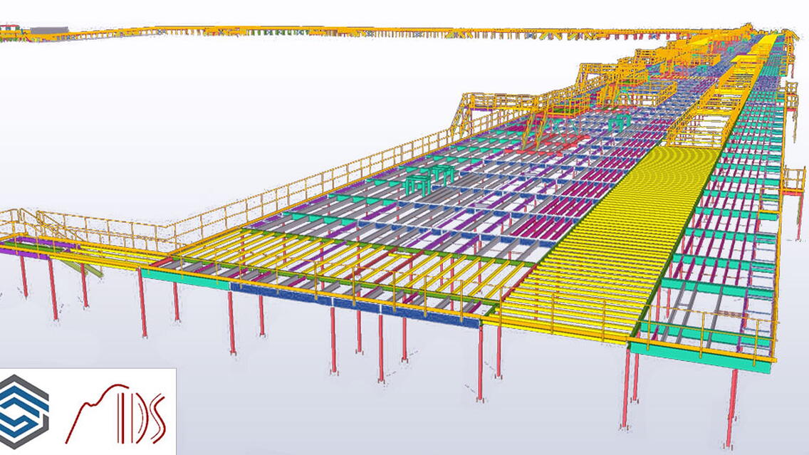
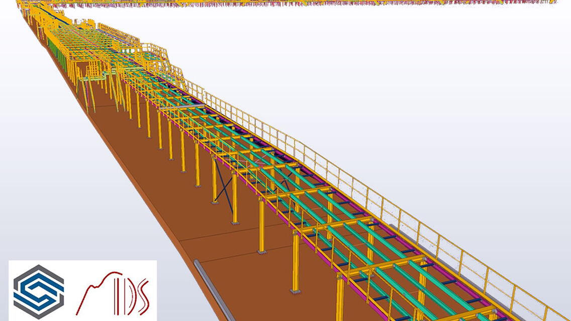
It is not the same on the neighboring floors. Part ’B’ has rough floor plan dimensions of 28 x 340 meters and a maximum height of 4.5 meters. The structure is mostly on one level with access stairs and ladders. The upper surface of the platform is not horizontal, but it matches the floor in a slope, which makes it about 1.7 meters in height per 340 meters in length. The third part, referred to as the ’Gallery’ connects the two previous parts and has gross dimensions of 6.5 x 360 meters. The structure is designed as an underground tunnel and in some places occupies the entire possible width and height. Additionally, the tunnel has a floor on several slopes, with the highest point approximately in the middle from which it descends in both directions.
Challenges
The complexity of the project is evident from the dimensions of the whole structure. The structure passes over many object dilatations. Another aspect that complicates the work is the installation in the already finished object, which has tolerances. The existing technology and shape could not be surveyed with necessary accuracy. The basis was, therefore, a 3D survey of the building – point cloud, common geodetic survey, and a rough measurement and control of dimensions at the time of installation. Designers had to constantly check these dimensions throughout the project and ask for clarification when necessary. The assembly took place in parts ’A’ and ’B’ at the same time. These two parts were then interconnected by the ’Gallery’. The designers also checked the requirements for uninterrupted heights and other geometric principles of the technological aspect.
The whole process ran continuously, i.e. during the assembly of one part, another part was still subject to discussions/reviews in terms of principles and assignments. There were also revisions along the way (technology, shapes, collisions with the building, and existing technology). It was, therefore, necessary to check the condition of the revised part, because often one revision affected the whole structure, which was at different stages of the process (statics, model, approval, production, assembly). During the design and construction, there were over 100 major or minor revisions! These aspects placed great demands on the coordination between the participants involved – structural engineers, designers, the customer, other professions, and, last but not least, the management of the project and installers on-site, who also used 3D data for planning and feasibility of assembly.
