General information about project:
Haramain high speed railway Medinah station, connection calculations and detailing works for steel structures. Erection methodology and calculations were also in the scope.
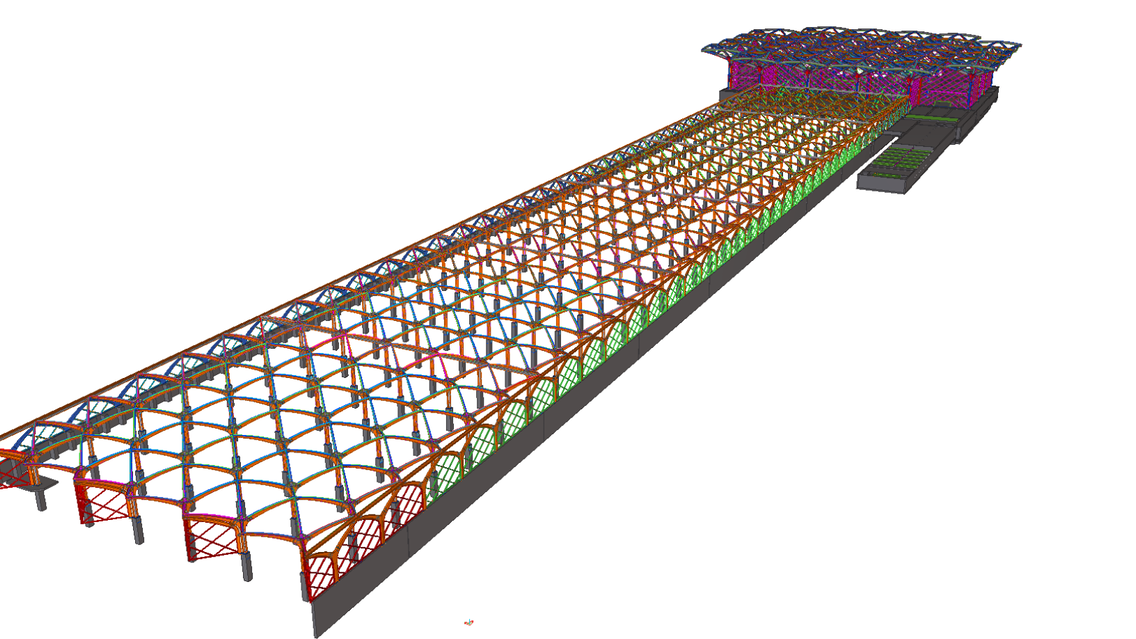
Steel structures were detailed as two models for the ease of work. Project has been started in August 2011 with Tekla 16.0 and finished in March 2012 with the same version. Medinah station has became the first station which has been approved and completed.
Project includes 3 groups of structures which are handled differently in detailing works.
1. Platform/Concourse columns and roof beams:
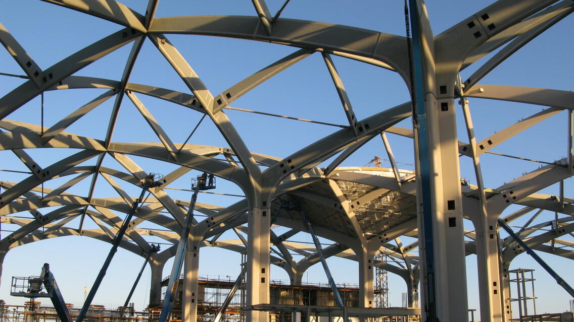
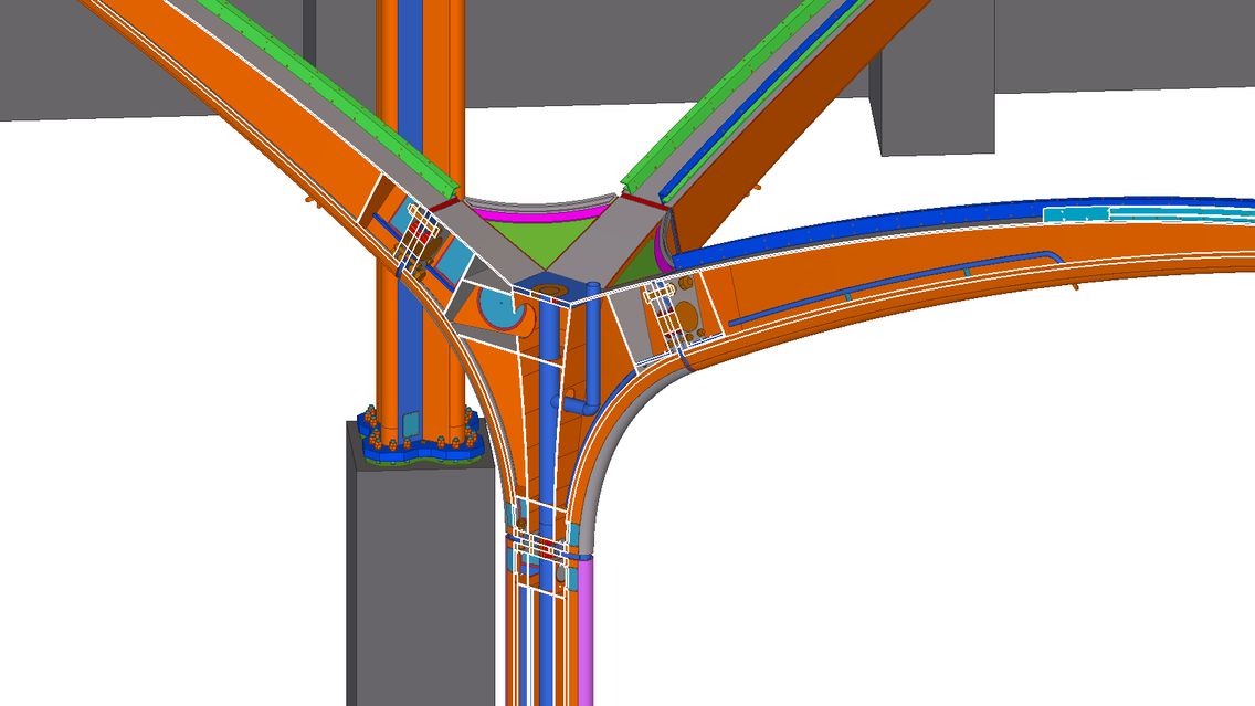
Columns and beams form continious frames. Columns are formed of 4+1 cell closed sections. The cells in 4 directions are morph into a beam then the side plates of these beams form out conical shapes. Lots of BIM works performed for accessibility of closed section connections and also MEP contents. All holes and conduits for MEP content were modeled inside columns and beams.
2. Platform and Concourse facades:
Connection design and modeling for these box section panels were performed according to the basic drawings.
3. Various structures inside Concourse:
Stairs, bridges, pavilions, floors and secondary mechanical supports were detailed according to the basic design drawings.
- Total Steel Weight : 11.200 t
- Length: 650 m
- Width: Platform 82 m, Concourse 165 m
- Height: Platform 9 m, Concourse 25 / 31 m
- Number of platform modules (1 column + beams in 4 direction): 216
- Number of concourse modules (1 column + beams in 4 direction): 32
- Number of parts in the model: 250.000+ (does not include dummy parts)
- Number of General arrangement and typical detail drawings: 320
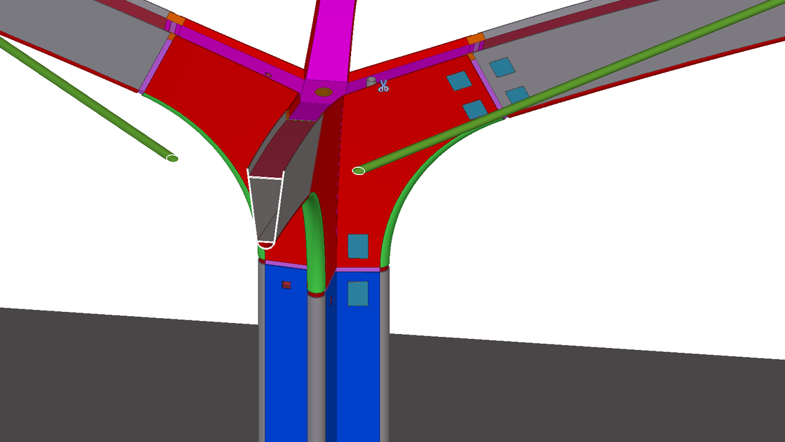
Modeling of conical side plates of closed section beams and column top parts.
The geometrical shape of each side plates is a small portion of a wide base conical shape like a chinese hat. We used our method to prepare the model and drawings for the conical plates. We did not used folded plate components and counter part handle shift methods which are already provided in Tekla. We prefered more precise and real parts in drawings. Also, our method worked with custom components better.
Using assembly – sub-assembly hierarchy to create GA drawings for modules faster and accurate.
We have completed the project in a very short time while working with other projects. To speed up the drawing creation, we used assembly – sub-assembly hierarchy to clone groups of members as given in sample drawings. Even the members are similar to each other, our client requested unique drawing for each module. Once we create a module drawing, we cloned the similars from it and correct the different components as cloning simple members like bracings, beams etc... Then we used the main assembly drawing as GA drawing. By this way, we could create all drawings from Tekla with no mistake and fast.


