Location
Within the Aeroplex hangar project, our company developed a structural system that utilized a large amount of land with minimal material consumption.
Of course, the parameters required by the local building rules were also fully complied with. The building is surrounded by existing and operating hangar buildings on two sides and a ground-story factory building on the south side.
Major enclosure dimensions
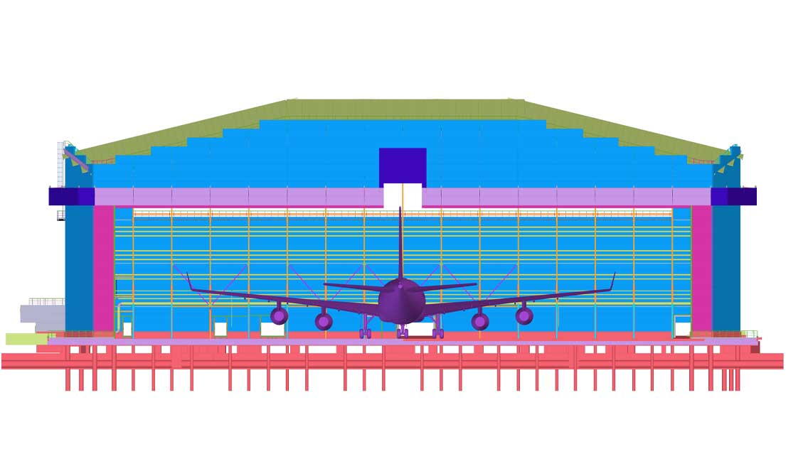
The single-aircraft maintenance hangar has a plan floor area of 8,272 m2 and a span of 90 m. A 75 m wide and 17,5 m tall four-piece hangar gate will be located on the north facade of the building. Above the gate structure, in the middle, is a tailgate with dimensions of 5 m * 3 m providing access to a vertical stabilizer, which, in a closed state, serves as the upper guide rail of the main gate. The highest point of the building is 31 m, and the shoulders are 23,5m. On the north and south facades, the corner of the hall was chamfered, which was intended to reduce the local wind loads and turn the gate to the sides.
Major support structure sizes
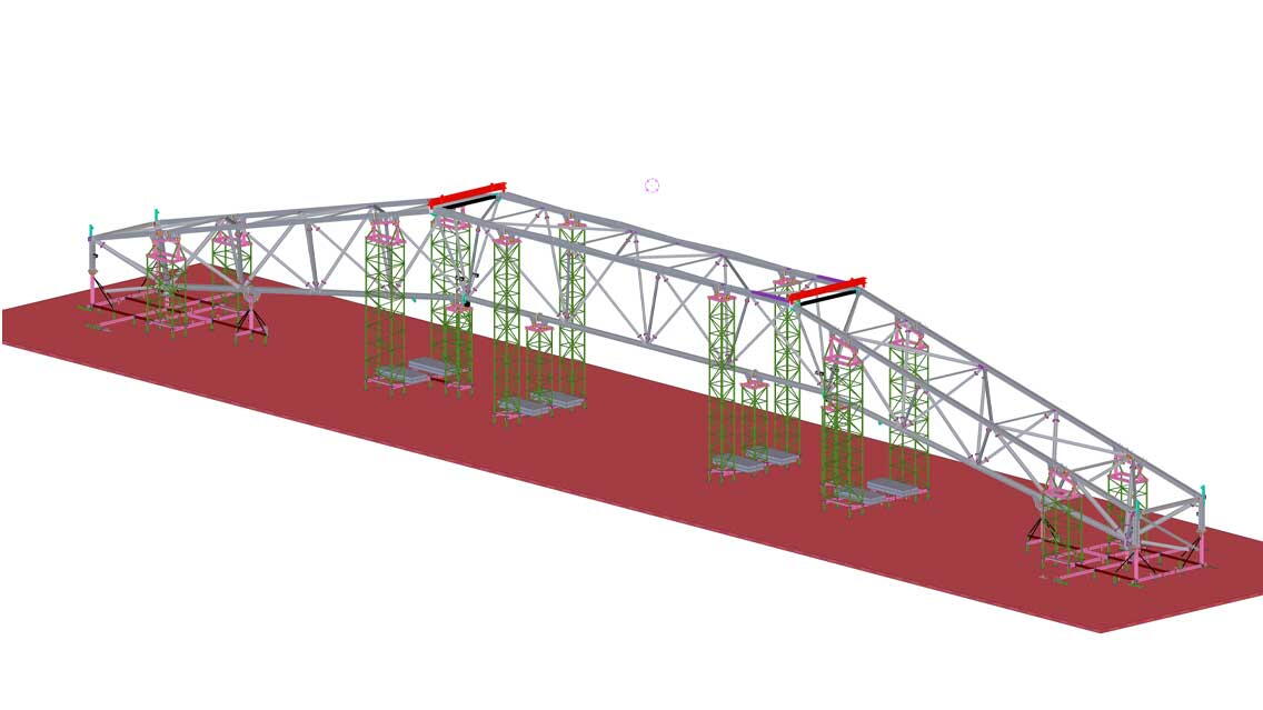
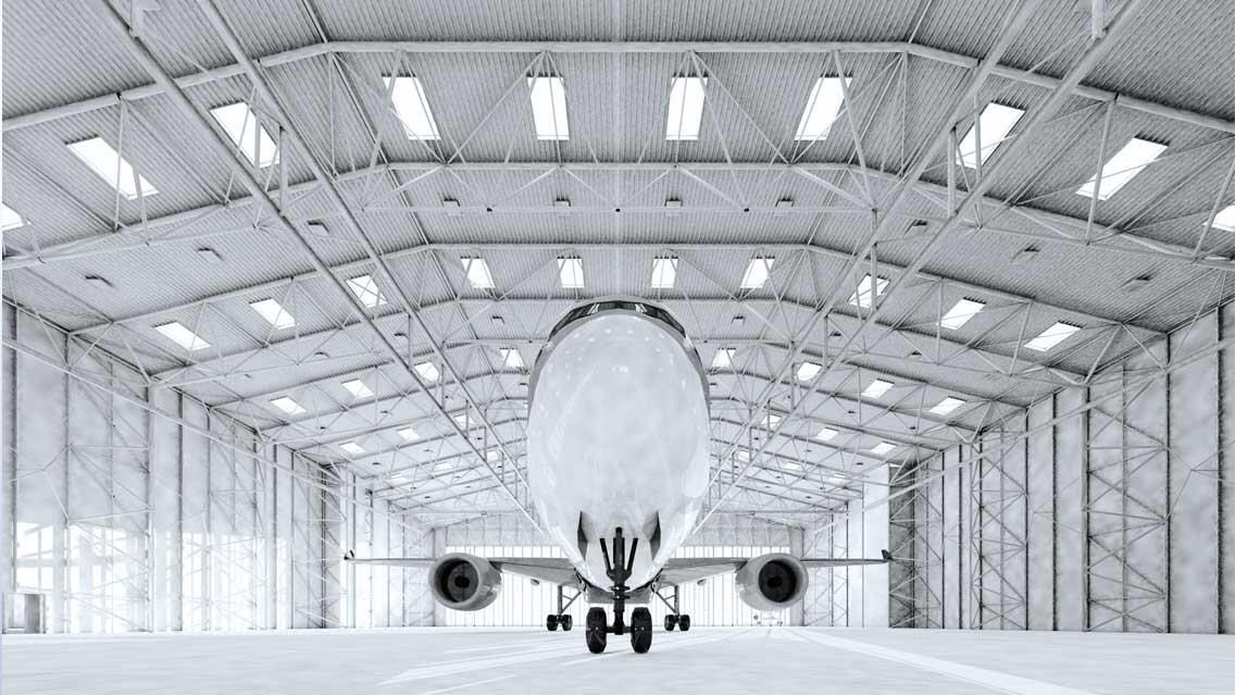
The hangar along the length, on two different height levels, has a crane design. Two gantries with a load capacity of 5 t will be installed on the two side tracks, while a gantry with a load capacity of 10 t will be installed in the middle third. The middle tracks for the cranes are designed as a suspended structure from the frames. We used parametric design tools to select the most optimal methods when designing the structural system’s geometry. The main structural system we created consists of 3-chord lattice trussed frames, which are located 11.5 meters apart, and between these main frames, secondary columns are placed. In the southern part of the back wall of the building, a flat lattice support system has been designed, which is stable in itself. The gate support structure functions as a unique three-dimensional lattice truss.
The foundation of the building is an industrial floor with bored piles at the frames.
The southeast corner of the building is a smaller service building outside the hall contour, measuring 6.7 m x 15 m in enclosure size. The 2 m cantilevering extensions serve as canopies.
The building floor does not follow the 40 cm slope of the site, so there are stairs and ramps when connecting to the adjacent buildings.
Preparation for fabrication
The fabrication preparation was done in a computer program environment developed by the manufacturer’s factory infrastructure, so there were opportunities to take advantage of the automated production, which optimized the time spent on cutting, and welding. In addition, we designed a factory assembly tool, which significantly helped to reduce the assembly and control measurements. Finally, the structure has been designed to make maximum use of the track’s cargo hold.
Assembly planning, Tool design
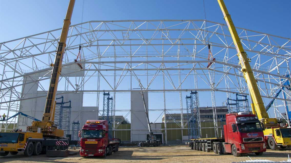
Examining the tight construction site during the design of the installation technology, our goal was to install the structure efficiently with low-capacity cranes and allow the paving to proceed at the same time with the cladding. We designed assembly tools to be used at all frame positions. Large-element lifts were performed in tandem lifting with two smaller capacity cranes, so it took less than six days to lift and complete the main girder. Due to the particular construction site, the 90 m beam had to be raised between the two buildings and built trussed pillars with a proximity of 10-50 cm.
The gate frame is assembled in the hangar in the horizontal position. It is rotated to an upright position in the first phase with the help of two larger and two smaller capacity cranes, after which the two higher capacity cranes are lifting it into place. Because of this, crane ropes do not need to be reconnected in subsequent stages. The installation of the hangar gate follows all these steps.
We were the first in Hungary to test and use the Trimble holoLens XR10 technology during the installation.
During the design phase, we used Tekla software, which helped us all create an efficient and economical project implementation from the planning and construction side. For these reasons, we consider the project and the entire team worthy of an award.


