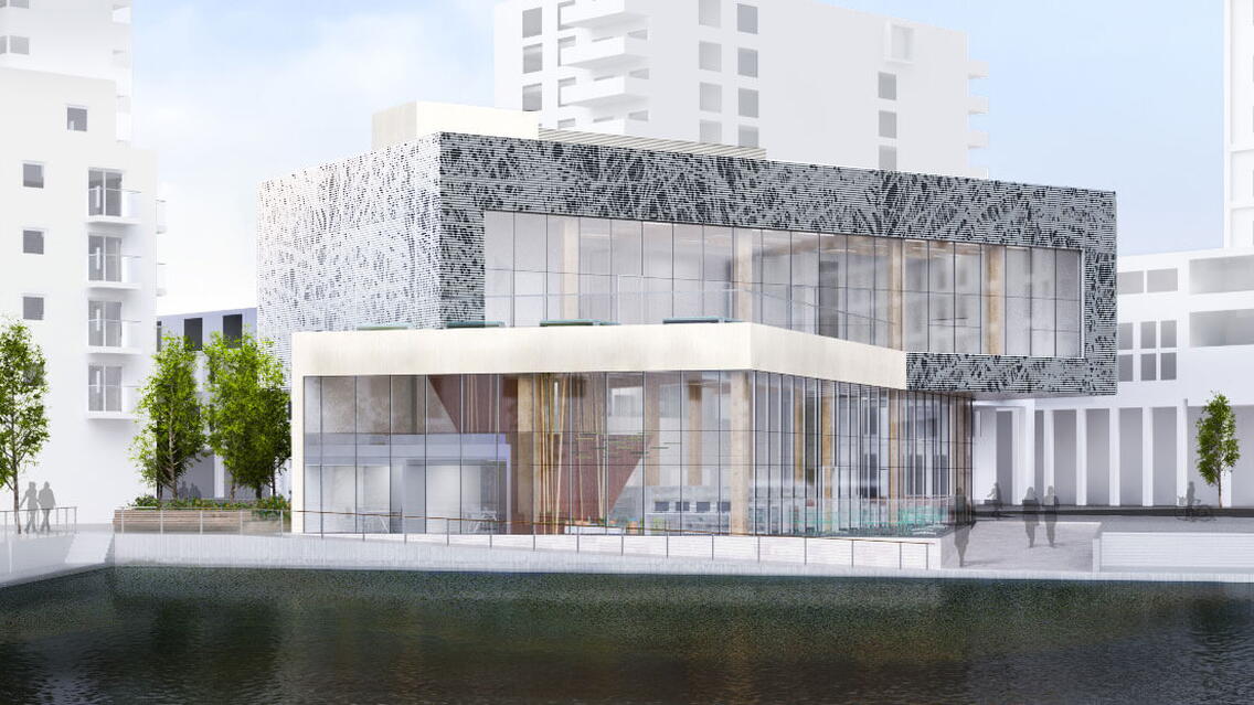
At the end of 2017 Bisset Adams won the RIBA Competition to design the new Southmere Civic and Library Building located at the heart of a major regeneration development in Abbey Wood, Thamesmead. The project was developed with Peabody, The London Borough of Bexley and the local community to generate this Lakeside Community Facility and Library. The design incorporates a welcoming, ‘transparent’ library, opening onto the new public square with views across the Lake to the Bow Arts Centre.
The architects concept is based on the idea of a Swan’s nest, reflecting the wildlife that inhabits the neighbouring lake. A swan’s nest pattern will wrap around the cantilevered upper level of the building and a bed of reeds will be created to divide the main space from the Children’s Library.
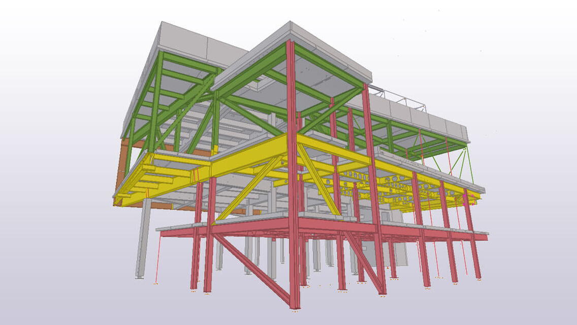
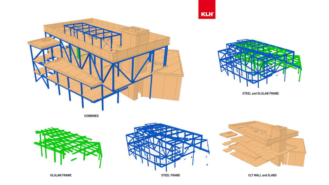
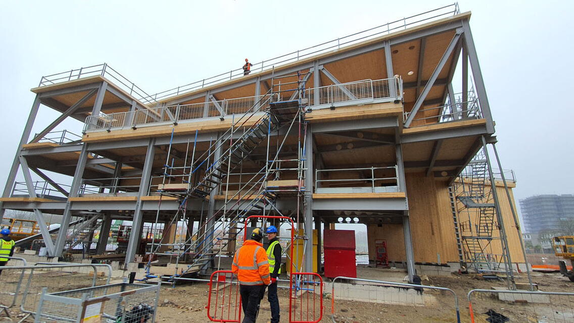
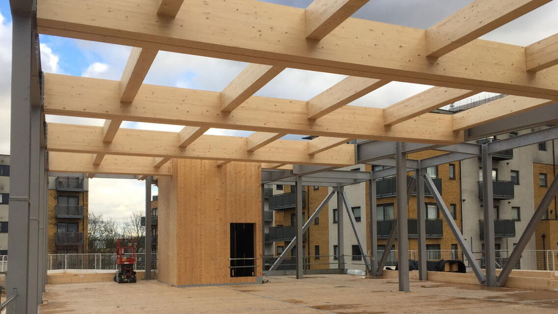
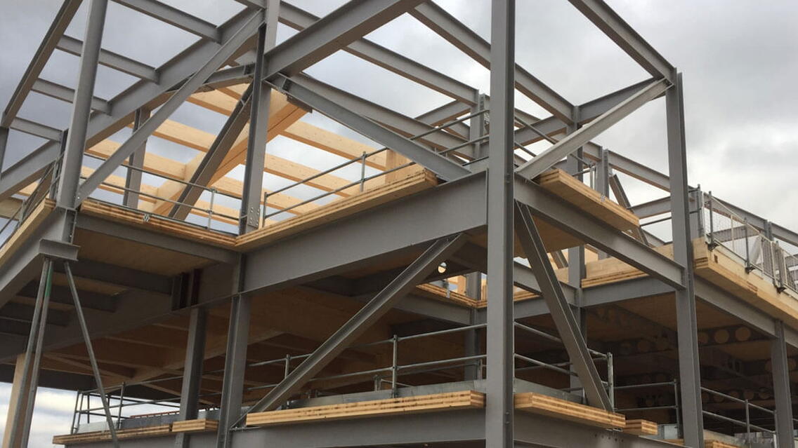
The Southmere library project is a true example of a hybrid structure, consisting of a concrete ground floor slab with an intricate cross laminated timber (CLT), glulam and steel superstructure with complex interface detailing and large areas of exposed visual grade timber elements.
The building has been designed to be a stand out piece of architecture sitting as a focal point within the square, lighting up at night to incorporate a playful element. Internally the spaces will be welcoming, light and flexible. It is envisaged that the building will act as the beating heart of the village to be used by the community, to inspire imagination, encourage learning and facilitate growth.
What were the challenges and what made the project successful?
The Southmere library project is a true example of a hybrid structure, consisting of a concrete ground floor slab with an intricate cross laminated timber (CLT), glulam and steel superstructure with complex interface detailing.
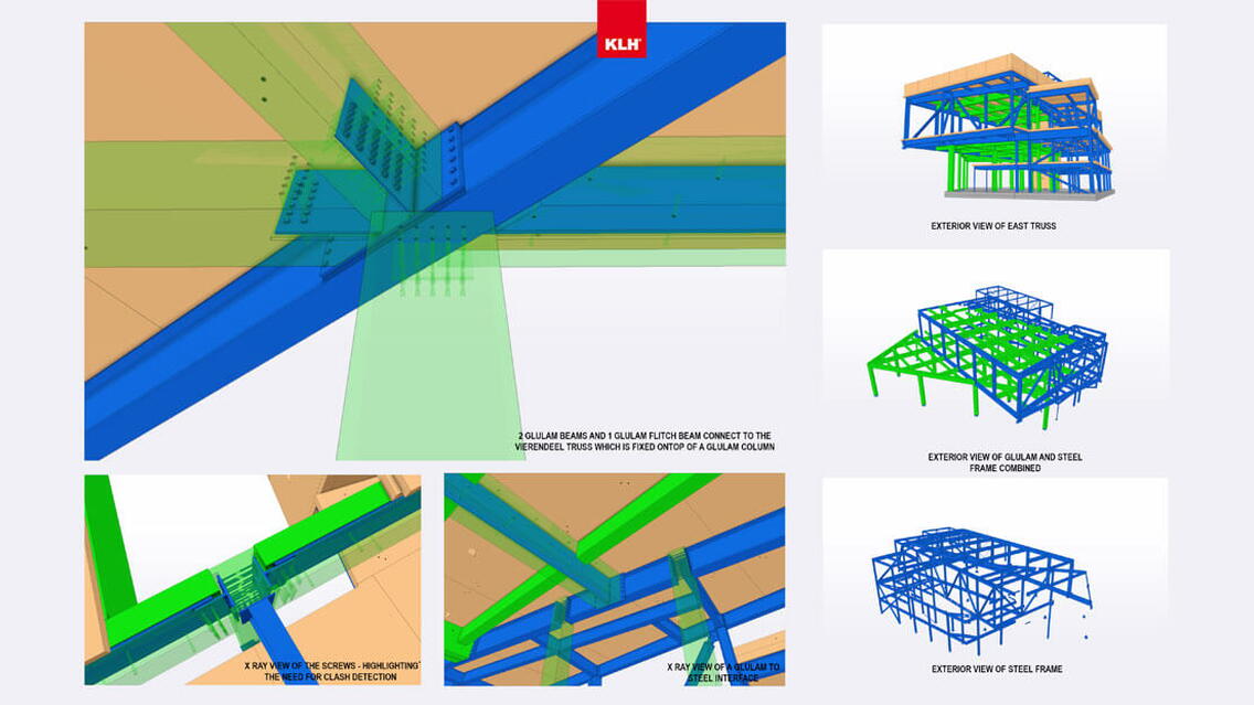
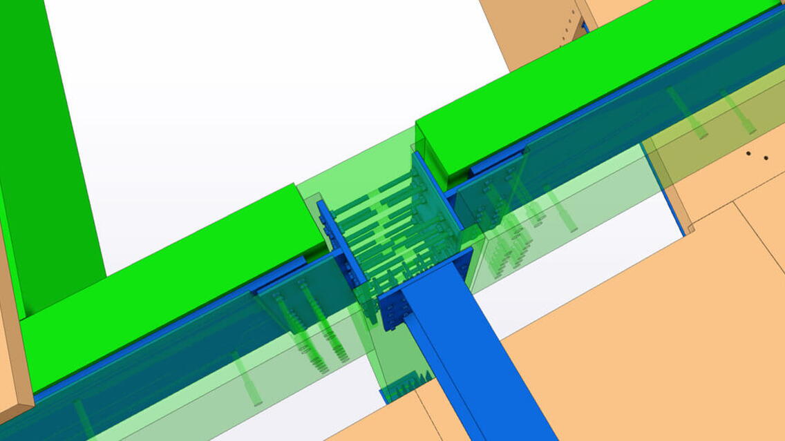
It would not have been possible to deliver this complex hybrid project in such a short period of time without the ability to add, extract and organize information in a 3D digital BIM environment. Tekla provided an excellent solution to detail and review the complex interfaces that consisted of multiple material types: The facility to quickly create custom connections sped up the connection selection and coordination process and enabled us to quickly review multiple options to develop the most efficient solution. Some of the more complex connection interfaces involved multiple steel/glulam elements connecting into a single glulam column. The excellent visualization facilities provided by the software greatly assisted in eliminating potential clashes in areas highly congested with screws and bolts fixings, thus minimizing the risk at the design stage of precious time getting wasted during the site installation.
The order process for the different structural materials required stringent coordination to ensure the correct information was approved, the appropriate components were manufactured and eventually delivered to site at the right time to match the installation sequence of the project. This was all possible by having the right tools available: which is why using Tekla to deliver the steel, AutoCAD Hsb to deliver the CLT/Glulam and Trimble Connect to bring these 2 software modules together was invaluable for the successful delivery of this project.
The project was ordered, and the components manufactured just in time which required that multiple order models be produced utilizing both software platforms. Trimble Connect was employed to overlay all these IFC models, to carry out clash detection, for 3D coordination and the preparation of the information for site installation and quality control.
Collaboration with our supply chain from the outset was key to ensure the correct fabrication workflows were in place to produce the structural elements in accordance with the project programme. The steel fabricator was fully aware about how the coordinated digital 3D information was going to be delivered, allowing them to use the Tekla model to check, extract data and fabricate the complex bespoke steel elements using the latest CNC technology.
The structure was designed and installed to tight tolerances to match the visual requirements of the architectural brief that included large areas of exposed visual grade timber which added further complexity to the project.
What benefits did utilizing BIM and Tekla software bring to the project?
The ability to create data-rich fabrication ready elements which are usable by manufacturers/fabricators
- Having lightweight and easy to use, data-rich IFC models for co-ordination and data extraction.
- Being able to visualize the complex design and make important decisions based on digital 3D information.
- Efficient workflow from the digital BIM model to fabrication ready drawings and CNC data
The project in numbers
- Steel tonnage = 125 tonnes (approx total)
- Number of steel parts = 1380 (approx total) 1470 total parts
- Number of assembly parts = 490 (approx total) 515 assembly parts
- Number of bolts Steel to Steel = 5150 (approx total)
- Number of Glulam components = 140 (approx)
- Number of CLT components = 300 (approx)
- m2 of CLT = 2260m2 (approx)
- m3 of CLT = 310m3 (approx)
- m3 of Glulam = 130m3 (approx)
- Number of drawings created = 1120 (approx total)
- Installation time = 8.5 weeks
- Crew size = 5 Specialist Installers + 1 Crane Driver
- Number of deliveries = 4 x Glulam, 8 x CLT, 8 x Steel
- Carbon sequestered = 105.6 tonnes (approx)
