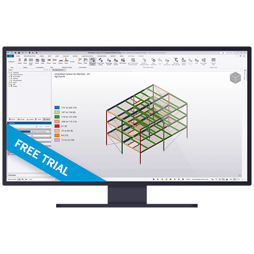
Why Tekla Portal Frame Designer?
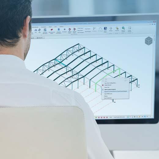
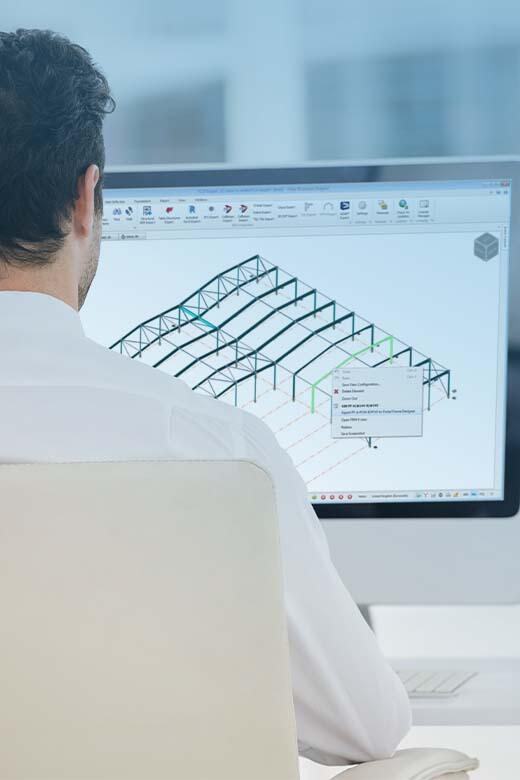
Tekla Portal Frame Designer is ideal for
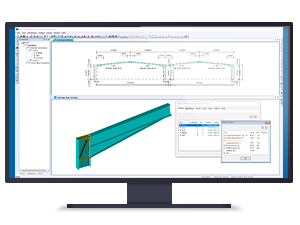
Analysis and Design
Easily produce both preliminary and detailed portal frame design options. Understand the hinge history of the frame including hinge reversal and spurious mechanisms. Fully interactive member stability checks. Automate frame sway stability checks (including SCI P292 full second order elastic-plastic analysis). Integrate eaves, apex and base plate connections to BCSA/SCI Green Book
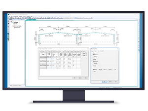
Modelling
Build your own steel portal frame. Choose from symmetric, asymmetric, propped, monopitch, mansards or flat top portal frames. Include valley beams, ties, cranes, floor beams and parapets as required. Select from pinned, fixed or partially fixed base conditions. Optimise haunches from rolled sections or plated sections.
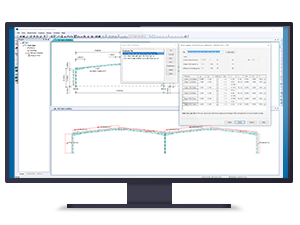
Loading
Apply dead and imposed load cases automatically. Calculate wind loading and snow loading to BS6399 automatically Easily apply notional horizontal loading for sway stability.
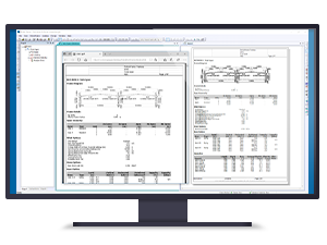
Documentation
Customise and export reports to Microsoft Word. Export foundation and connection forces to Microsoft Excel. Save all output documents in PDF format.
Why Tekla Connection Designer?
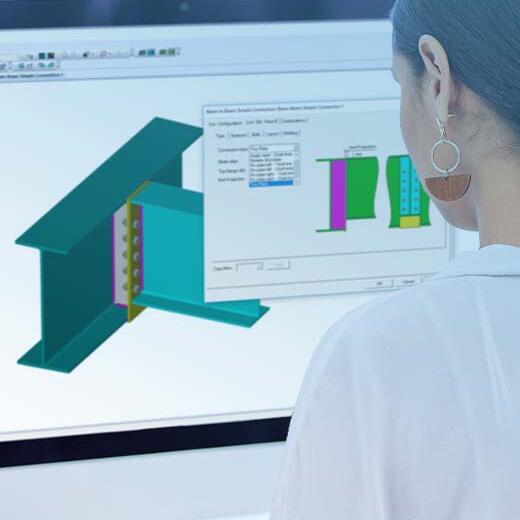
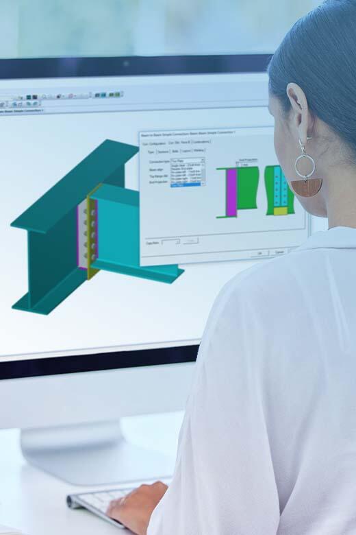
Tekla Connection Designer is ideal for
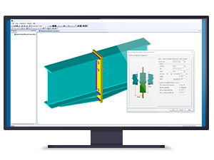
Moment connections
Beam to column connections including portal frame eaves connections. Beam to beam connection design including portal frame apex connections and splice connections. Applied design forces include moment, shear and axial force. Stiffeners including shear, rib, full depth, flange plate, cap plate, web plate and extension plate. Haunches from section cutting or built up plate.
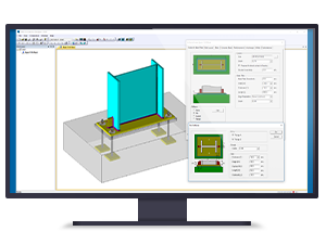
Column bases
Simple and moment steel base plate design with or without eccentricity. Applied design forces include moment, shear, axial and fire base conditions. Stiffeners include rib, gusset and flange plate. Pad foundation design with or without reinforcement. Individual or combined anchor plate check.
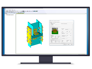
Simple connections
Beam to column connection design to both web and flange. Single and double sided beam to beam connection design with notching. Options include fin plate, flexible end plate, angle cleat and toe plate. Applied design forces including shear and tying force. Bearing and non-bearing column splice design with inside and/or outside flange cover plates.
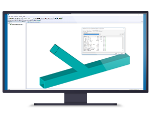
Hollow section connections
Welded tubular connection design with Y, X, K or KT configurations. Option for I or H section chords. International database of rolled I, H and hollow sections. Applied design forces include brace and chord axial loading and in-plane moment. Orientation of chords and braces can be rotated.
